
Many explorers in the Tesla alike fields have experimented with efficient L/c circuit methods in the past history. Those inventors where a great inspiration in better understanding this process . Such as Patents by Inventor John C. Bedini:
-Circuits and related methods for charging a battery Patent number 7990110
Bendini in his own ways took advantage of L/C circuits and specializes in BackEMF recycling of energy for efficient motor operations and battery charging circuits.
Issues with these devices is the requirement of a lab and a work shop. The every day average person can not always afford access to all requirements, Experiment with the similar devices and ideas may come limited as a result. Some of these generators are expensive,Noisy, big and heavy bulky.
I been searching and experimenting for many years, Seeking for simple yet easy creative methods for gathering a useful amount of energy by alternative means that could be accomplished in a realistic way. So I started to experiment and research what ever possible topic and related information within reach of my consciousness. I have tried. Trail and error. As a result of personal study and frustrations. This directed me towards the understanding of this method that can actually be practical. Not too big and no special requirements to build and operate. The amount of wattage this process generates, demonstrates the possibilities of this concept. Without the need for traditional batteries to operate as well. The process is self sustainable, Once started from an initial 12 volt charge of a few seconds (From a charged super capacitor bank) can be self powered once operating. With the help of a timer relay circuit that switches every hour from charge bank to run bank. continuously switching back and forth in this matter.
About Claims:
1- This process does not use any batteries.
Only source of storage is the internal circuit capacitors for DC and coils for magnetic AC storage.
That source of storage must be per-charged prior to start up. Such as making sure the capacitor run bank has the full charge. Similar to how one one would charge a regular battery and operate from it.
This process uses super capacitors to emulate the battery banks. We split the bank in two sections. The run bank and the charge bank.
2- This process offers over-unity without breaking any laws of physics.
This is a special linear type of over-unity. The effect of total output wattage is proportional to the requirement load. It will not just generate total power into a load that is not "asking" for it. And burn it out. As have been an issue for other over-unity goal motor generators from past "failed" inventors that have been haunted with this and similar issue and the same problems can be said with other related inventions/inventors in the filed of alternative power generation. where a massive output power burns out the input stages rendering a "perpetual" process null.
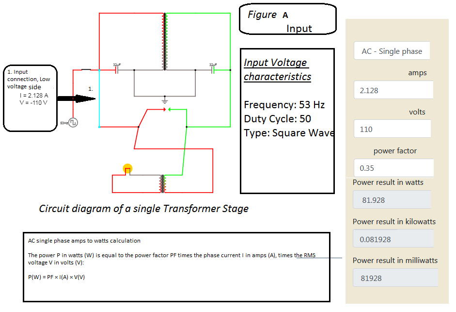
How ever with this new process, For example. Such as a light bulb only needing 50 watts connected to the output load will not see current spikes of more then the requirement needed. Even if this process can provide 100s of watts if such where needed by output load to glow light. (see fig)
Another way to look at it this. This process does not over load on itself with excess current. The process is perfectly balanced with the help of a dual tuned resonating circuit (see fig) along with the load current requirement. By the process of natural equalization between two different capacitor voltages combining two oscillating L/C circuits.
With this process, We are having always one of the two capacitors that are sharing common ground, They are both charged at much greater voltage difference potential between them thanks to the oscillations of the this dual L/C circuit and the efficient transformers transformer free V-I change. Those 2 capacitors are Joined (shorted) by a load, at each opposite ends, (see fig) Causing a very vast voltage imbalance between the two capacitors. This generates an imbalance of voltage between the load 2 connecting opposite points. As a result. The the local universe tries to maintain natural equalization (quantum) between two points in voltages, With all it knows, By quantum works. This process of natural equalization. Moves power to the running load, in between the two capacitor voltage points. At This stage. This is now load resistance generating current according to ohms law. power resides in that load. as a result from that perfectly natural equalization process happening between the load and two capacitor points.
How ever power does not just get made. You can not make power. We can Just transfer it from one type of system to another. We can only manipulate. it. We as of so far only know of the ohms law. So we can make an estimate based on what we know from ohms law assuming it is of similar in the world of quantum physics until someone can prove otherwise. This running process "manipulates" the equivalent of several kilo Amps from the quantum "Dimensions" in order to maintain "trying" and restore this perfect universal equalization balance of voltage between two points. (see fig)
This can be confirmed in a CAD simulation as the computer knows only the ohms law and since power has to come from somewhere. It calculates those "somewhere power" value equivalents to be in the kilo Amp ranges. If we could ever measure quantum energy with ohms law. Amusing we could.
Basic CAD circuit simulators can run and confirm this process method. As I have.
3- Each Transformer stage can generate up to 2.1 kw.
with calculated values, only an input square wave of 110 volts DC pulsed at 50-60 hertz with a duty cycle of 50 percent. 80 watts is needed to drive the process to a state of resonance. (see fig) Input low power drive, varying depending on where the oscillation cycle is at.
Input Power Calculations: 80 watts:
4-This process uses L/C resonance.
Taking advantage of super conductivity properties of a L/C circuit at the resonance 50-60 hertz point. The L/C stage becoming 0 ohms at this frequency. allows for a direct connection to be made at the DC point between the two capacitors connected at each end of the primary and secondary winding, joining together at ground point. The most profound result of this is the sudden effect of a low current being transferred to the high voltage side by a virtual direct DC path caused by the resonance effect at that very sharp specific tuned l/c frequency of 50-60 hertz. Tesla was very afraid of this effect of the human body accidentally suddenly being conducted as the bridge between the high voltage secondary low current side and the low voltage high current side while oscillating gives the human body a lethal shock of several kilo-volt at also high current.
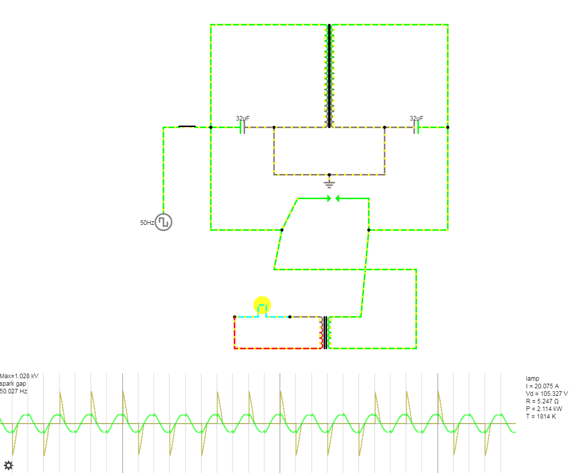
80 watts 110 volts pulsed DC(12 volt DC-AC inverter) is relatively low power in the primary side. When that 80 watts gets transferred over to the high voltage side and now we are reading simultaneously the same current reading on both transformer ends. How ever the high voltage side can get a whole Heep of extra work done at 1kv 80 watts. We then send this to a spark gap assembly that pulses this high voltage and very same current as the 110 side, but considered much stronger in 1kv oscillations! The spark gap feeds a regular AC high voltage to low voltage transformer operating in regular mode so it can steps down 1kv 80 watts equivalent power to 110 AC 50-60 hertz 2.1 kw power.
5- This process also utilizes Tesla's well known method of shorting a tuned L/C circuit.
With the help of the spark gap at just the right interval pulse frequency.When current and voltage are at its peek. At high voltages this "shorting" effect helps us extract even more watts out of the surrounding atmosphere (radiant energy, Such as nearby RF and magnetic fields but not limited to just such. All radiant energy, including, local scalar and gravity waves) for a moment, pulling it in along with the oscillation pulse cycle.
6- This process takes advantage of the negative resistance properties of the spark gap by operating in Region B. As a Negative Resistance.
See Fig 1, V-I Characteristics of Spark Gap
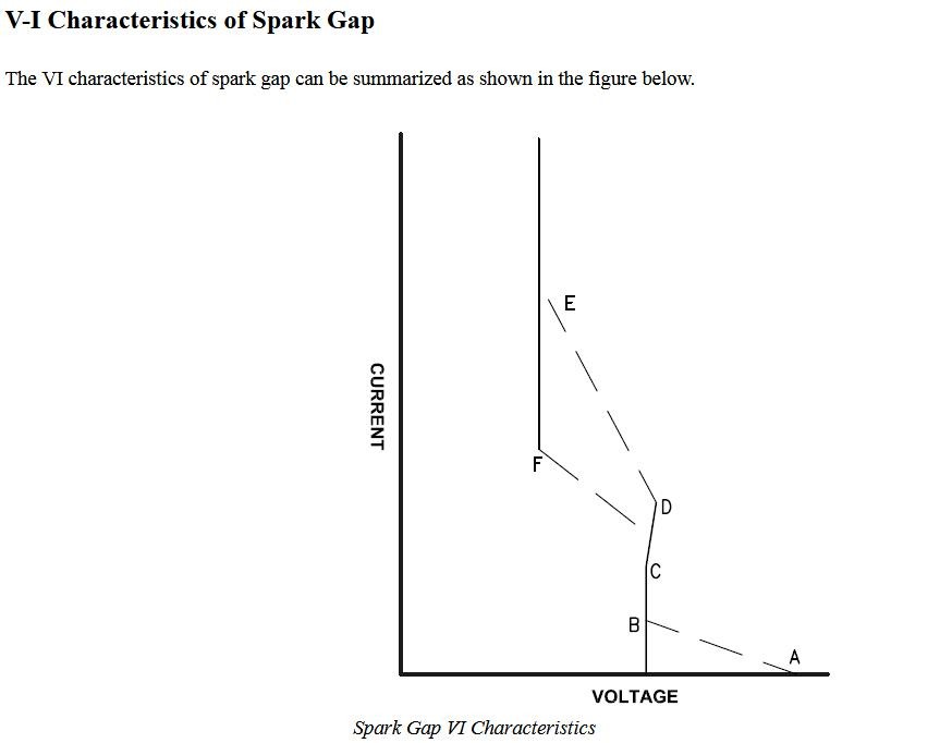
The various regions can be identified as follows:
Region A-B: At point A the spark gap starts the transition from insulating to a conducting state. The voltage at A is called the DC firing voltage of the gap. Between points A and B the device exhibits negative resistance.
Region B-C: In this region the device maintains a constant voltage across the terminals for a range of current.
Region C-D: This region The dV/dI is positive and the device exhibits positive resistance unlike region A-B.
Point E: At point E the current has sufficiently increased in magnitude enters what is known as the arc regime. In this region the potential across the spark gap is essentially constant at about 20V (independent of current).
Point F: When the current reduces to point F the arc stops. This point on the V-I characteristics is known as arc extinguishing current. The value of arc extinguishing current is around 0.1 to 0.5A.
If we observe the V-I characteristic . The current required to initiate the arc is greater than the current required to sustain the arc.
7- No matter what R value the run load is. The process locks L/C Stage oscillation at 1kv. Regardless if the load is using only 1 watt or needing up to 2.1 k watts,(The load barrier)
Thanks to the Spark gap operation of region B.
If the load barrier gets broken. or the process maximum determined by amount of transformer stages, The spark gap slows firing frequency as the voltage drops slightly below 1kv break for some longer period. As it takes a moment longer for voltage build up oscillations for form. (slowing) Spark frequency (de-tuning) and power intensity. there for forcing spark gap operation in Region C, As a regular positive resistance device.
Explanation:
The load barer with this process is maxed at being anything more then 2.1 kw for a single transformer stage. This was determined with the help of ohms law and internal computer calculations and simulations.
If the load barrier gets broken, The over- unity or power multiplication effect seizes. But circuit internal L/C oscillations maintains locked at lower voltage at 49 hertz or lower. Before the spark gap stage.
SOLUTION, Simply easing the load requirement for a few seconds will restore the voltage spikes and rise current oscillation charge up, the cycles speeds back to the tuned l/c optimal circuit value including the spark gap stage back in sync. And will again maintain over unity from that point on or As much "up to the load barrier point" needed to maintain load.
If more power is needed. One must think of adding more transformer stages to the process. Each transformer stage will generate an additional 2.1 kw in exchange for stressing the input power drive an additional 80 watts.
8- AS long as the 1 KV ring oscillation is maintained for Spark , Current amplification is greatly gained and operates steady.
Thanks to negative resistance of the spark gap and the shorting effects of a high voltage tuned L/c circuit at the proper resonating pulse rate. (see fig)
9- The Spark gap also acts as a high voltage limiter.
Pulsing no more then 1kv into a step down transformer when adjusted. A simple traditional transformer can step the 50-60 hertz cycle AC waveform pulses. To 110 volts 50-60 hertz power. That is compatible with "mains" home electrical system. And powering “free” watts to consumer devices and tools.
10- This process can operate without the spark gap but power amplification effects are greatly reduced.
Power output without spark drops to 10s of watts instead of 100 or more.(see fig) This process can operate solely based on the natural equalization effect of the quantum on its own. how ever. the spark gap stage is much appreciated and also utilized in helping and enhancing this method for a much greater result in power output.
11- The process can be self sustained(perpetual)
with the help of a simple generic low current control circuit, after an initial circuit start-up With a charged super capacitor 12 volt DC bank. Driving a local 50-60 hertz square wave oscillator able to handle at lease 80 watts of switching. (see fig) After 5 seconds or more. Enough oscillation cycles build up in the L/C, And phases with the tuned ring frequency. This brings the voltage ringing, to the spark gap 1kv break at 50-60 hertz and feeds a step-down AC transformer.
Explanation:
The circuit generator schematic values can provide power for 110 volts AC, 2.1kW per transformer stage . A load can operate from this such as a motor or power can be stepped down one more time to low voltage AC into a rectifier stage. Charging a super capacitor 12 volts DC bank. These 2 banks, Emulating the run battery pack, And charge battery pack. With This setup comes without as much of an internal resistance drag as traditional batteries do, for speedy efficient low resistance charging.
A slow speed generic timer circuit can switch relay between charge DC Super Capacitor bank and run DC Super Capacitor bank every few hours, This process of keeping the circuit charged and current amplifications going. In addition from self oscillating. Can use excess watts to power loads such as a light bulb or motor.
Regular ohms law calculations must be taken into account with variables such as how many transformer stage the process is going to take in order to determine how many times you need to be able to provide 80 watts for at lease 1 hour run time so not to drain the input power source that is not NEVER directly connected to generators output. Directly Looping the power is forbidden in physics.It just won't work This is the work around. As the input drains over time. We just need to insure we don't over load or drain the source before the switching gets done between the two power source super capacitor banks. The timer circuit directs the charging current to the non running power bank. And back.
12- This process takes advantages of using Super Capacitors as a power storage medium,
Eliminating traditional high Resistance internal battery charging And eliminating the need for a battery setup all together in order to operate this process.
13- This process could be used to power something very massive(secret) in the middle of nowhere.
With almost no limits as to how much output it can produce as long as you have the physical room for the batteries and all the needed transformer stages.

 Find Me On: