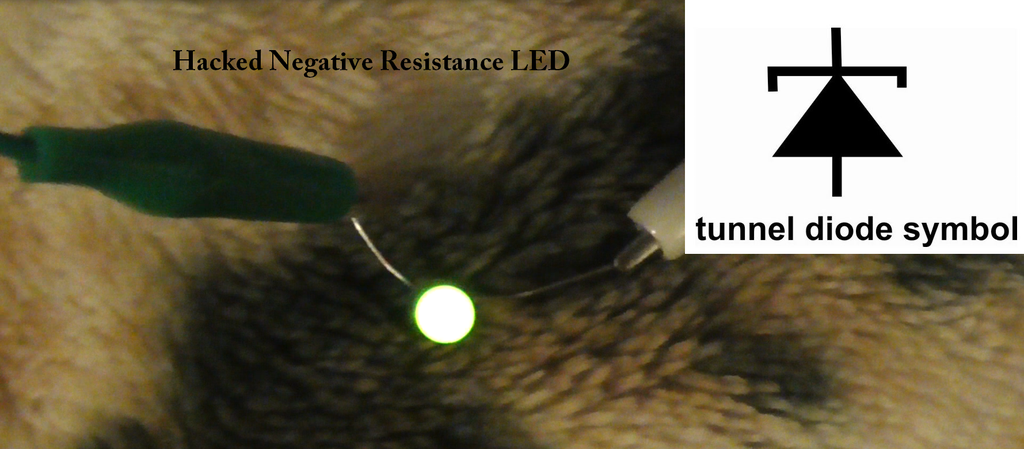
Simple Negative Resistance Amplifier LED

Hacked Negative Resistance Acting LED.

There is little talk today regarding negative resistance passive
components, Mostly because they where used mostly in the old days with
the early radar detector technologies, "Tunnel Diode"
Proved to be interesting in the day as they could be used as
oscillators and amplifiers as well. And worked perfect on the microwave
bands. But then semiconductors and transistors quickly
took over.
But negative resistance is still a rather interesting effect to study
and experiment with. (Rumor has it. That negative resistance devices
may even have anomalies dealing with the ohms law.) It can amplify
part of the negative AC current cycle where negative resistance takes
place within this repetitive cycle. But in the case of a diode, needs
some sort of DC bias voltage to work as an AC amplifier. It does
not have to be very much at all!
So where can you find negative resistance?
-Florescence Tubes
-Neon Lights
-Tunnel and Microwave/Radar Didoes
-Home made Cat Whisker Copper Oxide Didoes
-High Voltage Spark Gap ( Tesla took advantage of the negative
resistance of his spark gap so he could amplify the AC currents
generated and received from his wireless from a distance, Given he had a
great ground connection. )
As you know, All the above mentioned have several or more interesting
oscillator and amplifier circuits if you want to search for them. For
example, In the case of oscillation, Usually called "Relaxation
Oscillator" As a result to the negative resistance properties of the circuit.
So today I'm going to show you how to built the Words most simple and
safe low voltage resistance amplifier that can amplify AC with the help
of a half charged 1.5 volt battery (DC bias) and light
up an LED
Parts List
1. Two or more identical LEDs
2. 1 or more diodes (Ge type preferred)
3. 1.5 Volt Battery
4. Two or more clip jumper connection cables
5. FRS Radio or Similar (For providing nearby source of low power RF also known as a type of AC)
Step 1: Cooking a LED

First thing we need to do is slightly cook a LED until its light starts
to change color by getting darker and tinted but not completely cooked
and burnt out.This only takes a couple of seconds. I find it works best
with a 6 volts battery pack. I connect the battery pack to the LED
light for about 5 seconds as I watch the color change then quickly
disconnect to not let the LED completely burn out and go dim. It may
take a few tries to get it right so it is a good idea to have some
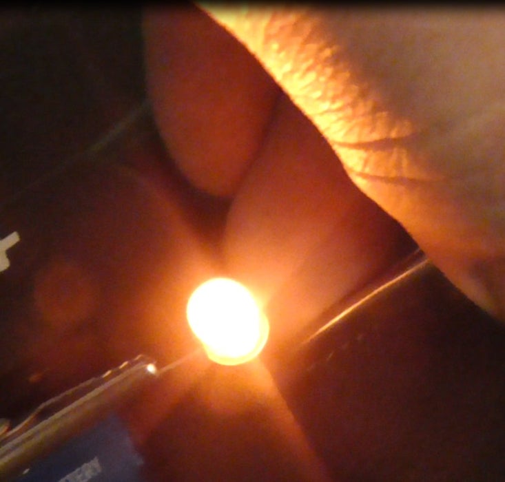
spare LEDs on hand. This yellow LED turns dark orange after a few
seconds of 6 volts!!
Congratulations, We just built our negative resistance device!
Step 2: Putting It Together.
Take your partially cooked LED and connect the anode long side to the
cathode "line" side of a regular diode and together with the help of
the wire clips. Then connect the two remaining ends contacts together
with another wire clip (the loose length instead of just connecting the
two diodes together, The wire length between the two diodes act as a
sort of crude loop antenna) Now take your 1.5 volt battery and connect
the + side of the battery to the plus side of the circuit( the longer
LED pin) and do the same with the negative side on opposite end. You
will notice you do not have enough power to turn on the LED light. This
is normal. The DC battery will be our amplifier DC bias power source.
Step 3: Testing the Circuit
Experienced users may skip this part. If you have a regular LED and
have never played with simple RF diode detector circuits. May I
recommend that you take the extra step to first experiment with that.
Simply connect a regular LED to the circuit instead of the cooked one.
Place your FRS antenna 1 inch away from the LED. Press the transmit
button and you will see the LED faintly light up. This is because LEDs
are also diodes and this only diode circuit acts as a crude AC to DC
power supply (rectifier circuit) energized by the nearby RF as a form
of AC provided by the FRS radio or other nearby transmitter. Cool!
Now run the circuit as intended with the cooked LED and you will notice
much more brightness! As it behaves like an AC amplifier. read bellow.
Now running the circuit.
Make sure everything is connected as simple as a circuit this is.
Connections may get loose. Now push on the talk button of your FRS
radio or similar transmitter ( The 6 inch *give or take* connecting
wires act as a good resonant antenna at the UHF frequencies) You will
notice your cooked LED lights up nice and bright at normal color and
you can pull the radio several inches away before it dims out once it
is lit and starts amplifying! That is, the LED is acting as a negative
resistance diode amplifier and doing the job. Amplifying the RF/AC
signals with the help of small DC bias supply and making it's own LED
emit a bright light as a side effect.
Step 4: Experiments to Try
Try adjusting and vary the low voltage DC bias to find the "sweet" spot
where AC amplification (LED brightness) is at its best. Perhaps a
variable resistor.
Try replacing the battery with a small capacitor. Then the circuit
becomes in part a DC power supply provided there is nearby RF/AC to
energize it. What I'm getting at is you may be able to use the
circuit's rectification properties and DC stored in capacitor as the
source of DC bias and still get a very nice bright LED without actually
needing the 1.5 Volt DC bias battery at all!! No it's not over unity
I'm sorry but still very interesting stuff!
And many more negative resistance experiments? Usually these kinds of
experiments require much higher voltages in order to drive neon and
spark gaps etc and can be dangerous and intimidating. This is a great
introductory way to get into it without getting hurt and learning about
negative resistance and or RF.
Still not convinced?
Food for thought. Florescence tubes need a ballast, That is an
Induction coil acting as a current limiting filter to counter the
effects of negative resistance within the tube. It takes more power to
activate the tube then is needed to keep it bright. Without a
protection ballast. The negative resistance would cause the AC currents
inside To amplify to a point it would damage the tube. Even sudden
fluctuations in input voltage could instantly destroy the florescence
tube. With that logic let's experiment some more with our modified LED.
Bring your radio antenna about once inch from your LED. turn and keep
pressing the talk TX button, After a moment or two. The LED glows
brightly, Slowly as your still holding the TX button, Bring your radio
a few more inches away. Perhaps 6 inches. You will notice the LED
remains very bright and can hold this brightness a short distance away
from the RF source without flicking off. As we are then observing the
negative amplifier properties of the LED quick in, Needing much less
power to stay light up then it needs to activate. ( Acting very much
like a Florence tube)
Try again. Repeat with a regular LED and you will notice the effect to
be greatly diminished or not noticeable at all! (Your LEDs can always
react and flicker close by to RF without any modification such as
turning it into a negative resistor as I describe in this article.) The
amplification properties of a negative resistance device is what is
really interesting!


